
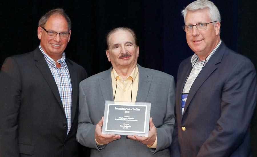

See the latest Sustainable Plant of the Year winner
Any milk dryer operation uses a lot of energy, and when you have the biggest operation in North America, you use…a lot of energy.
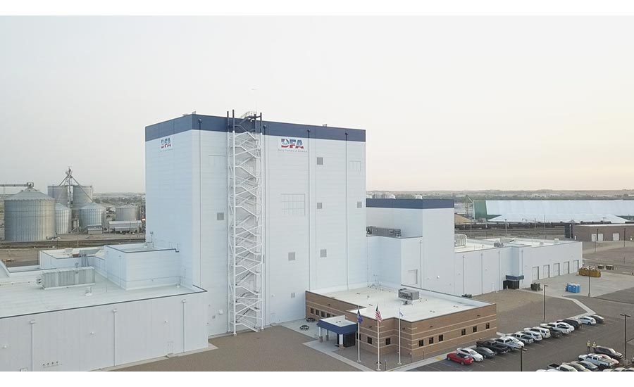
Specifically, in the case of Dairy Farmers of America’s (DFA) new Garden City, KS, plant, we’re talking a connected load of 18.9 megawatts, (even though it uses less than half of that). But what’s amazing about the SQF-Level 3-certified plant is how tightly coordinated every part of it is in creating a highly sustainable operation—and using the least amount of energy possible to produce exceedingly consistent, high-quality powdered milk products with practically no scrap.
Article Index:
Thanks to the cooperation between DFA’s project teams and the design/build/engineering capabilities/expertise of Shambaugh & Son, L.P., an EMCOR company, engineering firm of record, this DFA operation is such a fine-tuned operation that it can run for days and days at a time—and do clean-in-place while the facility is still making product—all while recycling heat, water and energy, and keeping energy bills as low as possible.
But saving energy isn’t the only reason FE editors voted it as the FE 2018 Sustainable Plant of the Year. Like many new plants that are built today, sustainability includes on-site wastewater treatment, the way the plant was built, its location, acquisition of materials, and so on. But one thing sets this operation apart.
What makes this operation especially important and memorable is the totally integrated controls system, because without it, maintaining product quality and consistency while minimizing energy inputs would be like shooting a moving target while the shooter is moving as well. In this case, a distributed control system (DCS) coupled with a manufacturing execution system (MES) not only control the process, but also all the mechanical systems, based on the needs of the process: steam generation, HVAC, air compressors, wastewater treatment system, and so forth. Why? Because making consistent milk powder is so highly dependent on the environmental conditions that they need to be controlled in concert with the process. Otherwise, innumerable product is scrapped and energy wasted.
Basic facts about DFA’s facility
- 330 S. US Highway 83,
Garden City, KS - 270,000-sq.-ft. facility on 165 acres
- Processes 4 million pounds of milk/day from 12 member farms
- 520,000 pounds of milk powder per day
- 490,000 gallons of raw milk storage
- 350,000 gallons of process water storage
- 166,000 pounds per hour of raw milk processing capacity
- 600,000 gallons of treated water storage
- 18.9 megawatts connected
- 4,800 boiler horsepower
- 1,100 tons refrigeration capacity
- 750 air compressor horsepower
- 500,000 cu. ft. per minute of air distribution
- 1 million gallons/day water treatment plant
- 22.5 miles piping, 530 miles of electrical wire
- 92 miles of electrical conduit
- 890,000 hours worked
- SQF Level 3 certified
Competing with the world
The Garden City milk drying plant is the newest addition to the more than 40 DFA manufacturing facilities nationwide. With the slogan of “quality in-quality out,” the product produced in the plant ranks among the best of world-class milk powder producers.
Attention to detail will pay off, according to Alan McEntee, DFA Garden City project program manager. “We will be competing with the best in the world at what we do in Garden City, so we will exceed their standards. We have extraordinary milk quality from our local members, and it will be processed in a best-in-class facility…a formula for product that will be recognized around the world as the best of the best.”
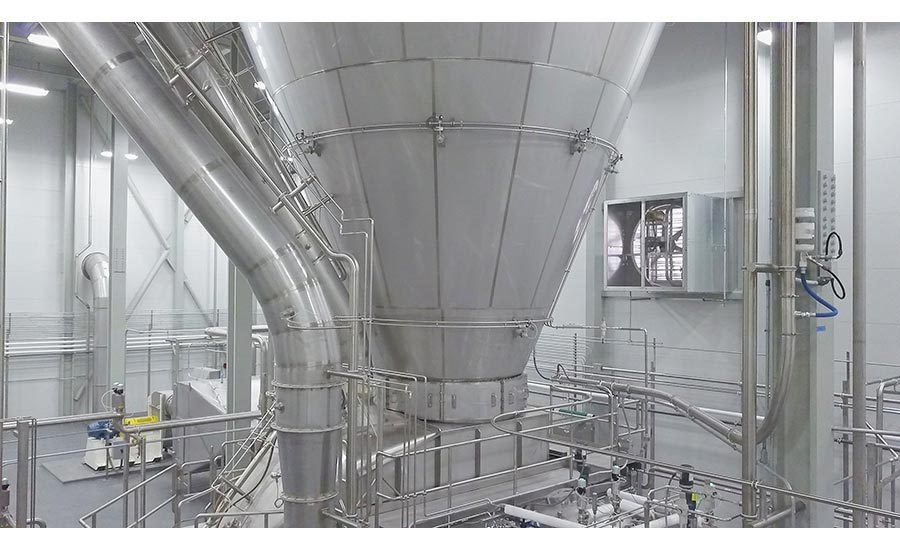
DFA’s new facility occupies 267,000 square feet on a 165-acre site and stands 157 feet tall in what was a southwest Kansas cornfield. Designed to operate 24 hours a day, seven days a week, the plant receives 84 tankers every day from local daily farms. At 50,000 pounds per tanker, that’s 476,000 gallons per day. The facility has storage for 4.1 million pounds of milk, 350,000 gallons of processed water, 60,000 gallons of pasteurized cream, and it produces up to 9,000 25-kilogram bags of low-spore milk powder per day. That’s equivalent to about 500,000 pounds (US) of milk powder a day.
With a new project, DFA and Shambaugh had a clean slate to put together a sustainable dryer facility. With DFA joining the newly launched Project Gigaton initiative to reduce operational emissions, the objectives were obvious. Every design aspect of the building and the site, the materials, equipment and the management of water and energy resources must have an inherent ability to contribute to curtailing greenhouse gas levels and use of fossil fuels.
“Project Gigaton is a Walmart initiative established to avoid 1 billion metric tons (a gigaton) of greenhouse gases from the global value chain by 2030,” says Jeff Johns, Shambaugh senior vice president (project executive). DFA joined the community of suppliers in 2017 with a commitment to reduce 10 million metric tons of carbon through on-farm practices and technologies that include covered lagoons and anaerobic digesters, cow activity monitors, and overall continuous improvement in on-farm management systems.
Perfect controls = perfect quality
Like a conductor has control over the constituent ensembles within an orchestra, DFA’s distributed process control system coupled with the MES system is literally directing all the subservient control systems within the plant as described earlier. These controls are critical to producing a consistent, high-quality milk powder, while keeping energy and water usage as low as possible.
Not so long ago, a typical DCS controlled the process, but not much else. DFA and Shambaugh automation project teams needed to find a system that not only was capable of talking to other systems (such as HVAC, boilers, wastewater treatment, air compressors), but would also be fault tolerant with potentially unstable power. Rockwell’s PlantPAx DCS was chosen for its ability to communicate via Ethernet to other controls. In addition, its automation platform makes use of standard library objects, which make programming and configuring the system easier, as these tools are built on years of experience in hand-coding specific control applications.
Thin client software from Automation Control Products (ACP), which became a Rockwell Automation company in 2016, was used throughout the plant to provide a lightweight HMI so operators could have access to the centralized PlantPAx DCS from any location in the facility. “The Rockwell PlantPAx system controls the process, HVAC, mechanical and wastewater systems,” says Jason Paxson, Shambaugh controls engineering operations leader (automation & controls lead). “With all these systems being tied into one supervisory control system, the ability for load shedding and energy management is in place.”
The PlantPAx system runs on a plant-wide uninterruptible power supply (UPS), which ensures the automation system will continue to run through brownouts, power surges and outages. A plant-wide Ethernet system, using EtherNet/IP at the controls level, ties the Rockwell DCS to the mechanical controls systems and to the manufacturing execution system (MES).
With a complex system designed for maximum flexibility, long process runs and energy management, the complication of managing potential product loss is magnified. Keep in mind that a very miniscule variation in water content in powdered milk can make a huge difference in profit or loss.
The MES was designed to capture real-time data from the process automation system. Strategic identification of necessary locations for instrumentation or segregated processes allows for the capture of real-time information to feed back to the operations staff to maintain continuous target process line uptime objectives. Daily production reports are published, based on individualized “batches” moving through the process systems, allowing raw materials to finished product traceability.
These reports rely on process line measurements (flow, temperature, pressure, volume, solids level, fat content) captured by the system’s instrumentation equipment, which were researched and developed exclusively for this project. With the implementation of the MES, the ability to monitor the potential of valuable product making its way to each segregated drain area was developed, allowing for immediate correction by the automation system if detected.
Energy savings
As one might expect in a modern facility, many common approaches to minimize energy impact in a facility. Among them are high-efficiency motors, variable speed drives (VSDs), low-emission burners in the boilers, area-specific LED lighting, a heat rejection recovery for environmental media and water heating and seasonal adjustable variable air volume control.
Also installed is a plant-wide power metering system. The power metering system covers all equipment and monitors power by process segments.
“We recover heat in a number of ways within the plant,” says Brook Schroeder, P.E., Shambaugh senior mechanical engineer (mechanical lead).
All boiler make-up is preheated via stack economizers that recover waste heat from the boiler exhaust. Waste heat from the air compressors is used to reheat dry compressed air to generate maximum volume and prevent condensation on the distribution piping. Additional waste heat from the compressed air system is used to heat the boiler room as well as offset other outside air requirements for the boilers. The cooling side of certain process make-up units are operated during cold spells to preheat make-up air as well as reduce the cooling load on the refrigeration system, adds Schroeder.
All mechanical pumping systems (boiler feed water, condensate return pumps, potable water distribution, process water distribution, chilled water distribution, cooling tower water distribution) in the plant are modulated based on pressure so that only the minimum amount of pumping energy is expended, Schroeder says. Multiple pumps are used to provide additional turndown within the system, as well as to allow pumps to be turned off when loads are reduced. The process HVAC system incorporates active pressure control throughout so supply and exhaust fans are modulated as needed to maintain proper pressures while providing just enough cooling or heating to satisfy the space.
The way mechanical equipment is operated also keeps energy usage low. As indicated above, multiple units were utilized in nearly all systems to allow better load matching throughout the operational range of the plant. Mechanical system pumps, evaporative condenser fans, ammonia compressors, air compressors (250 hp x 3 compressors), boilers (125 hp x 3 boilers), and wastewater lift station pumps (125 hp x 3) are staged and ramped to maintain constant supply pressures, levels and/or temperature. Wastewater treatment blowers (250 hp x 6 + 150 hp x 2) are staged and ramped to maintain prescribed dissolved oxygen levels.
A closer look at mechanical systems
The plant’s steam supply is generated by a system of three 1,600-hp boilers, which provide up to 161,000 pounds of steam as needed. The boilers include energy saving features such as VFDs, oxygen trimming, flue gas recirculation, nitrogen burners to reduce carbon footprint and stack economizers. Capable of a a 24:1 turndown rate, the boilers are sequenced and take their marching orders from the DCS.
The boiler system was designed to communicate with and accept data from the process control system so that the boilers could be pre-acted if necessary, says Schroeder.
“We also took steps to make the control system as robust and responsive as possible so that we could avoid implementation of the pre-action system, if possible,” says Schroeder. “The desire to avoid implementation of a pre-action protocol stems from a concern for overcomplicating the system. We have found in practice that staging the boilers has maintained stable header pressures throughout the operational range of the system. Staging has proven to be responsive during low load periods while still being able to aggressively react when large loads occur.”
The plant’s compressed air system consists of three 250 hp efficient rotary screw compressors with the capacity to provide a total of 3,100 cu. ft. of air per minute as needed. Each compressor is cooled by the central refrigeration system and is fitted with ducting to recover waste heat.
Waste heat from the air compressors is used to reheat dried compressed air to generate maximum volume and prevent condensation on the distribution piping, says Schroeder. Additional waste heat from the compressed air system is used to heat the boiler room as well as offset other outside air requirements for the boilers.
Energy is saved by optimally running the compressors only as needed to maintain the system pressure at 125 psig. During the design phase, operation of the compressed air system was simulated for several types of systems, including systems that were all VFD driven, systems that were all capacity modulated based through valve operation, and hybrid systems. The most efficient operation was achieved using three compressors with valve capacity modulation, adds Schroeder.
The plant’s HVAC system provides MERV 13 filtered clean air for wet processing, evaporator and dryer tower spaces via building integrated supply plenums. For critical packaging areas, HEPA filtration provides improved product quality control. Variable volume make-up air operation and active pressure control for the process spaces allow supply and exhaust fans to modulate airflow to match space ventilation and temperature requirements without excessive fan energy. The peak air makeup for the system is more than 500,000 cu.-ft. per minute.
“Multiple compressors are used to handle the maximum capacity of the plant,” says Tom Aurich, Shambaugh vice president Refrigeration Group (refrigeration lead). This also provides a measure of redundancy in the event of equipment failure or planned preventative maintenance. The compressors are sequenced to address the load imposed on them from the process. A centralized PLC system is used to provide the highest system operating efficiency possible, adds Aurich.
“Within the Rockwell distributed control system we have partitioned areas for process and mechanical systems,” says Schroeder. The HVAC system is controlled by the mechanical side of the Rockwell system. Both sides communicate with each other seamlessly, allowing for plant programmed access and control from all interface locations. The plant is able to select what can be controlled or monitored from each interface.
Saving energy and water in the process
Reducing the dependence on water from the municipal water system is important, so water reclaimed from the separation and drying processes is cleaned and reused. Approximately 90 percent of the water removed from the milk (aka cow water) in the evaporation process is recovered for reuse in the plant, says Schroeder. This reduces the demand on outside water sources. Water recovered from the process is supplemented with reverse osmosis-treated city water. RO treatment is minimized by allowing a controlled amount to bypass the RO system. Only the minimum amount required to satisfy the process equipment is treated by the RO system.
RO treated water is used as make-up to the boilers, cooling towers, and evaporative condensers so as to reduce chemical treatment loads as well as maximize cycles of concentration, says Schroeder.
Process water push valve arrangements were designed into the entire liquid process portion of the plant, allowing every product transfer to and from the silos, to and from process systems, and to and from intermediate work-in-progress to be captured for re-introduction into the process system.
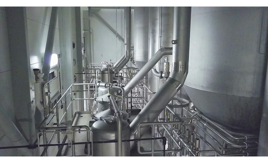
According to Mike Parsey, Shambaugh vice president process engineering automation & design (process lead), approximately 85 percent of the total water removal occurs in the separation processes before final spray drying.
In many milk drying operations, evaporators (pre-final drying stage) are started and stopped, causing initial product concentrate that is low in solids and is unusable as product—which means energy was used in the process, and the unusable product must be disposed of somehow. To keep this from happening, Shambaugh engineers used product recovery tanks, which store the lower solids produced during evaporator startup, when building solids, and during shutdown as water is pushed through the evaporator to clear product from the evaporator.
“During startup of the MVR/TVR evaporation processes, condensed milk solids levels are monitored by a density meter,” says Parsey. Condensed milk solids that are below the desired feed-forward setpoint for the dryer are routed to a rework storage tank. These recovered solids are bled back into the evaporator feed tank, after the evaporator has been running forward to the drying process for a period of time.
Parsey and his team sized the recovery tanks to handle the volumes produced during these startup/shutdown times and allow for the re-blending of the product back into the evaporation process.
“In our experience, the MVR/TVR evaporators have the capability to discharge condensed milk at a solids level range of 48 to 52 percent, depending on the milk powder to be produced,” he says.
For the milk separation process, the incoming, un-separated milk stream is directly pre-heated against the outgoing separated milk stream, says Parsey. “We have found nearly 90 percent of the available heat is recovered utilizing direct regeneration.”
The incoming milk feed stream to the evaporation process is indirectly preheated with the condensate (water removed) from the milk in the evaporation process. Nearly 65 percent of the available heat in the condensate is recovered into the incoming milk, he adds.
In addition, the design included start-stop bins to handle the first powder produced in the dryer, allowing the moisture content of the powder to be set to the correct specification.
The start-stop powder, similar to the low solids concentrate, is collected and re-introduced to the spray drying system, once stabilized production is achieved, saving energy to replace the lost production of off-spec product.
“We have found having the processing capability to capture/reprocess (1) start-up low solids condensed produced by the evaporation process and (2) start-up powder produced by the drying process, allows a 99-percent-plus recovery of the start-up products to be achieved,” says Parsey. In addition, he says the spray drying operation has the ability to remove water up to a rate of 19,000 pounds per hour.
Site-related sustainability
If you look at the map, Garden City might at first seem to be in the middle of nowhere—but it’s actually in the middle of cow country. “Transportation efficiency was a major factor in site selection,” says Jeff Johns, the project executive. Due to farms’ proximity, truck routes and time on the road have been slashed by hours and days. Cutting fuel usage also translates into a direct reduction in carbon footprint, making a sustainable difference in tomorrow’s agricultural environment.
Speaking of site-related issues, storm water is captured in an underground piping matrix, and a no-irrigation specialized landscaping was designed to reduce dust and prevent insect infestation. Storm water is collected in a detention pond, which filters into the ground water system via dry wells. Heavy storm events raise the detention pond level to a discharge overflow that drains into the Arkansas River via a short ditch.
The developed site was landscaped with granite river stone certified quarried less than 1,000 yards from the property. The stone eliminates the need for topical irrigation.
Building materials were also chosen to save energy. The roof is constructed of a minimum of 4-inch rigid insulation covered by a 0.060-inch thick white thermoplastic TPO membrane, says George Bachnivsky, NCARB, architect, vice president, director Food Processing and Advanced Manufacturing Group, MSKTD & Associates, Shambaugh subcontractor and architect for the DFA project. The thickness and color allow the TPO to reflect harsh sunrays instead of absorbing them. This reduces the heat load on the building, therefore, reducing overall energy costs. TPO is also 100 percent recyclable. The TPO was installed using wide rolls, which reduced the number of joints on the surface, allowing for less dirt and debris build up. This means less water usage during periodic cleaning on a food plant. The welded seams create an impermeable, monolithic surface for superior leak protection. The durability and versatility of the TPO reduces maintenance requirements compared to other roofing systems.
The majority of the exterior was constructed using energy saving insulated metal panels (IMPs). Each panel contains an advanced polyisocyanurate foam core with the highest thermal value commercially available in order to drive down energy usage and utility costs, says Bachnivsky. The panel skin system provides a complete air and moisture barrier.
The exterior panels’ light color minimizes heat gain and reduces energy costs. Additionally, the inter-locking and thermally broken panel joints eliminate thermal bridging, which in other types of construction is a source for energy loss. In order to minimize trucking costs the panels are designed and shipped in the maximum lengths permitted on the road, which in turn minimizes stacked panel joints, further reducing the issue of thermal bridging.
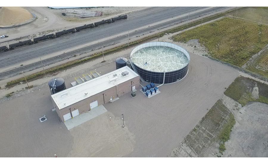
The facility also has a 2.5 million gallon wastewater treatment plant, which was a necessity as Garden City didn’t have the capacity in its wastewater treatment plant to handle the biological load. DFA agreed to build the facility, and it uses membrane bioreactors and UV disinfection to discharge any left-over wastewater from the facility.
There are four process flows at the DFA Garden City Operation:
- Milk Path: Receiving Bays → Raw Storage Silos → Milk Separators → Raw Milk Surge Tanks → Standardizing Systems → Standardized Milk Surge Tanks → MVR / TVR Evaporators → Dryer Feed Tanks → Dryer Feed Systems → Drying Chamber → Baghouses / Fluid Beds → Powder Bins → Bag Filler or Bulk Filler
- Cream Path: Milk Separators → Cream HTST Systems → Cream Storage Silos → Cream Load-out
- Lactose Powder Path: Bag Unloading Station → Powder Storage Bins → Loss-In-Weight Addition Systems → Standardizing Systems
- Cow Water Path: MVR / TVR Evaporators → RO Water Polishers → UV Water Treatment Systems → Chlorine Injection Systems → Process Water Storage Silos → Process Water Users
Resources:
- “Minimizing Energy Use in Milk Powder Production using Process Integration Techniques,” Chemical Engineering Transactions, The Italian Association of Chemical Engineering, Vol. 29, 2012.
- “Predict the future: Get control of your process,” Food Engineering, April, 2015.


