Food Safety
Put positive pressure on facility airflows

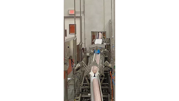

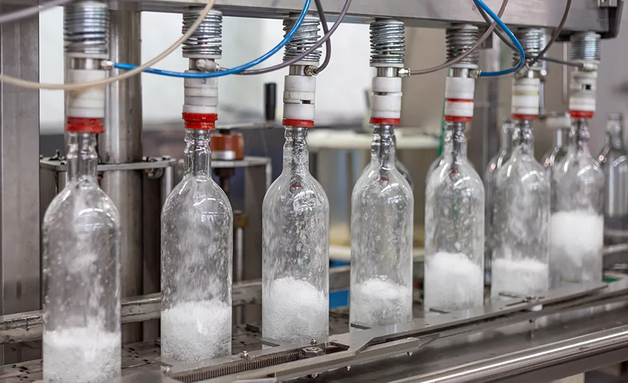
Food at its most vulnerable point in the process is where your operation needs to be the cleanest. For example, the filling and sealing of yogurt cups and the packaging of cooked lunchmeat are applications where food has already gone through a kill step(s) and must be kept clean until it’s sealed and ready to go out the door. With a filtered, positive air pressure in a clean room, bacteria and other airborne contaminants (e.g., mold spores, viruses and allergens) can be forced outside or into “dirtier” areas of the plant where air quality is not as critical.
Article Index:
- Tools to test or design new airflow systems
- Filtration versus energy usage
- What about an older facility?
- Clean air is everyone's responsibility
There are several ways to ensure airflow is optimally designed to keep clean areas clean. Building a plant with a “straight-through” design layout or separate facilities can do the trick. But for older plants, some changes might be in order. Clearly, each plant—whether it’s in the planning stage or already in existence—needs to be scrutinized by experts who understand airflow and have methods to quantify airflow patterns.
Several factors influence proper airflow design in a new plant. Mike Follmer, Hixson Architecture & Engineering vice president/project architect, lists several key considerations:
- What kind of product is made at the site? The specific food group the facility will be handling will determine how zones of control should be applied and, therefore, how the building’s airflow should be coordinated. For example, the airflow needs of a raw meat facility will be different than those of an RTE meat plant or pasteurized dairy processing facility.
- What production volumes will be handled?
- What risks are inherent with the product/process?
- What are the sanitation methods and protocols?
- What are the adjacent spaces, and how might they affect the area air handling system?
- What are the air pressurization requirements? It is necessary to achieve the correct balance between supply air and exhaust air in each space to maintain proper pressurization and, in turn, reduce or eliminate undesirable conditions. Establishing zones of control helps prevent unwanted contaminants from entering into clean areas and guides the placement and size of air supply and exhaust throughout the facility.
- What openings exist throughout the facility, and how might they affect the system?
Delving into these questions, and understanding the needs of the facility as a whole, enables planners to “pull apart” the building and see how the components need to work together, adds Follmer.
The primary considerations regarding production space air system design involve the separation of raw versus finished product and filtration requirements based on product vulnerability, says Mark A. Hoffman, SSOE Group department manager. “Depending on the product and production methods, it may be possible to design zones with the same filtration requirements, but the systems also should be designed according to relative room pressurization, with the highest pressure in the cleanest room and the lowest in the least clean.” However, rooms that house the production or packaging of RTE products like lunchmeat need appropriate filtration and air change. A 90° or even 180° turn in the flow pattern could also be workable, as long as appropriate production separation is maintained, adds Hoffman.
“The primary consideration is to prevent air from flowing into the high-care areas from the low-risk areas,” says Donna Lorenzen, The Austin Company chief mechanical engineer. “The level of filtration required can vary, depending on the final product and phase of production.”
For instance, while it might seem a new straight-through plant design would enable a single air-handling system to cover the entire facility, this usually isn’t the case. Lorenzen cites one good reason: “It is not desirable to have one system for an entire facility because that would require the system to be designed to the most stringent area or function, and the entire plant would be shut down in the event of an equipment failure or malfunction.”
“Theoretically, one system might be able to work if the airflow is designed properly,” says Joe Sunnarborg, EVAPCO sales engineer. However, using a single system connects raw and cooked rooms to a common duct system, which can lead to cross-contamination. Also, maintaining the correct room pressure, temperature, humidity and filtration level is much more direct if multiple systems are considered. Finally, Sunnarborg adds, with a single system, the whole process would need to go into cleanup at the same time. With multiple systems, this is not an issue.
“Separating air distribution systems based on pressurization and filtration concerns is common, and often necessary, especially [with] sanitation and allergen control,” offers Frank Mangin, Haskell group vice president, AE services. With highly clean processes (e.g., extended shelf life [ESL] milk), a separate air system is almost certainly necessary. Sometimes, temperature requirements may dictate separate systems (e.g., one or more of the bulk raw ingredients may not need cooling, but the finished product does). Some plants have a variety of environments from clean to dirty (e.g., raw product, cooking, packaging and finished/packaged product). These areas typically have differing levels of cleanliness requirements, resulting in varying degrees of filtration and pressurization relative to each other. For example, if the outside air has a relative pressure of zero, the various areas of a processing plant may have the following relative pressures to the outside air:
- Raw product/ingredient storage: +1
- Cooking: +2
- Filling/bottling: +3
- Finished/packaged product storage: +1.
“Separate air systems allow all these spaces with different environments [temperature, filtration, humidity and pressure] to be served by the most effective type of system for that application,” adds Mangin. “However, to keep differential pressure relationships, air will flow from one space to another, so there will often still be air relationships between spaces, even if the air systems are separate.”
Tools to test or design new airflow systems
When designing a clean airflow system for a new plant, Hixson considers the design requirements, looking at factors such as temperature, humidity, filtration, pressurization, sanitation methods and time period, maintenance access, human comfort, etc., explains Follmer. A variety of options can be provided to processors, depending on the system involved.
Tools to design and test airflow systems are often available from several sources. They vary according to function and application. “Spreadsheets for calculating pressure difference and airflow requirements are commonly used,” says Haskell’s Mangin. Clean room and other air terminal design guidelines can assist in laying out air terminal devices to ensure the air is filtered properly. For example, ASHRAE standards and guidelines can assist in a variety of design tasks such as the selection of appropriate air-moving and filtration equipment and configurations. A number of duct calculation programs can assist in determining system pressure drops and sizing fans. And, computational fluid dynamics (CFD) programs can be used to model a space thermodynamically. In the past, these programs were expensive, labor intensive and required a high skill level to use them. However, CFD programs have been used more often recently and for more practical applications.
Most equipment providers, such as EVAPCO and Camfil, have software tools to help size systems. “Generally, EVAPCO sizes hygienic air handling units that will hold the proper room temperature and humidity levels based on the size and temperature of the space the unit is serving,” says Sunnarborg. “The size of the room also determines how much fresh air needs to be brought into the space through the hygienic air-handling unit to keep the room at the desired pressure.” Other factors affecting the amount of fresh air needed to pressurize the space include the number of openings in the room to adjacent spaces, as well as any type of process exhaust.
RTE areas require higher levels of filtration—at least a MERV 14 filter—and sometimes even HEPA filters, says Luke Facemyer, Stellar vice president, refrigeration design. Air pressurization is also critical, with the cleanest areas (RTE) requiring positive pressurization to keep filtered, conditioned air within the space and unconditioned or unfiltered air from adjacent spaces.
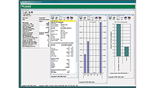
Sizing and predicting the lifetime of filters are also important factors in the design of clean air systems. Camfil has proprietary LCC (life-cycle costing) modeling software that accurately predicts the performance characteristics of almost any air filter on the market today, says Mark Davidson, Camfil USA national accounts district manager for the food and beverage segment. “The software takes into account the outside environment in which the filter will operate, as well as the operating characteristics of the air-handling unit itself, such as system airflow, filter area, return air rate and hours operated annually.”
The software provides engineers with new tools, Davidson continues. For example, the software shows what the real-life average pressure drop, airflow, filtration efficiency, service life and energy demands will be on the system based upon the particular filter(s) selected.
Davidson points out a real-world example. A common design calls for two pre-filter stages with a final filter stage downstream of the coil. Using LCC software, an engineer could discover there is a filter on the market capable of handling the pre-filter load in a single stage with half the pressure drop of the more typical two-stage pre-filter systems. Going further, the software shows there is a MERV 14-A filter that will last one year in service under the stated conditions, with an average pressure drop much lower than previously considered.
Filtration versus energy usage
There are many filtration options, from the type of media used (e.g., fabric or carbon) to efficiencies (low-, medium- or high-efficiency particulate [HEPA] air filters) and ease of maintenance (roll filters, pre-filters/final filters and a myriad of filter housings and locations that can affect labor costs for replacement), says Haskell’s Mangin. All these options, plus additional variables, can affect energy usage, procurement and maintenance costs.
Tight construction between spaces with different pressure and cleanliness requirements reduces the potential for cross-contamination when pressure differentials are interrupted—which they will be for material/personnel flow and, in some cases, during high wind conditions, adds Mangin. Most of the time, the same air-handling unit is used to control temperature, humidity, pressure and filtration. Using a separate unit for filtration can be effective when airflow needed for filtration is much higher than that required for temperature, heat and pressure control.
Lower velocities can reduce filtration energy costs, but the tradeoff may be a higher installation cost, says Mangin. To a large degree, the cross section of the air handler dictates the size and cost of the unit. The larger the cross section, the lower the velocity and the less energy required to move air through each section (e.g., filter, cooling coil, gas furnace, etc.). Energy costs can be predicted using an hourly analysis program for heating and cooling loads that takes into account the airflow and pressure drops of the air filtration equipment. This is done by creating a thermal and airflow model of the building and running an actual analysis based on weather data.
“As the old saying goes, there’s no such thing as a free lunch,” says EVAPCO’s Sunnarborg. “The best way to limit energy use is to make sure filters are changed based on the intervals specified by the filter and/or the equipment manufacturers. Also, it is very important not to specify a filter that is overkill for the application. Keeping filter velocities as low as reasonably possible saves energy over the life of the unit because of the reduced air pressure drop.”
“Many filters are manufactured with a low initial pressure drop, but once a filter is installed in a system, it loads with dirt, and the pressure drop increases,” explains Camfil’s Davidson. “This is where the ‘tradeoff’ concept originated. To achieve a higher filtration level, you’ll need a higher-pressure drop filter, and you’ll spend more in energy to push air through it. However, some high-performance filters develop a very long, slow loading curve that minimizes that tradeoff.”
“The filter area must be designed with face velocities that maximize the lifetime of the filters and minimize pressure losses through them,” says The Austin Company’s Lorenzen. “Adding pressure differential gauges to individual filter banks is an inexpensive tool to aid the maintenance staff in monitoring filters for replacement.”
What about an older facility?
If an older facility does not meet GMPs, getting an assessment or survey of the current system and comparing it with its original design is a good place to start. “I would survey the plant to determine what the current temperature, humidity, filtration [cleanliness] and pressure conditions are, how they compare to what the equipment was originally designed to achieve and what the facility’s current criteria are,” says Mangin.
According to EVAPCO’s Sunnarborg, “A great place to start is to take air samples and actually do a physical walk-through of the plant to determine the direction of airflow from space to space, even though a computer program may be able to model this situation.” Some problems are more or less obvious, he adds. “Most older food plants are negative to ambient [airflow] for no other reason than the fact that, over the years, exhaust fans have been added to spaces, and the air has not been made up.”
“The physical condition and cleanliness of the HVAC equipment, the process space and the process equipment can tell a great deal about the airflow patterns and quality of the airstreams,” states Lorenzen. “If record drawings are available, they should be reviewed along with the survey to determine any deficiencies and possible remedies. An air balance test of the existing HVAC systems and measuring space pressurizations also are recommended.”
CFD modeling is possible, but is often considered an extra expense and can be time consuming. “We first determine if the plant has a filtration efficiency standard based on sound scientific principles or as required by a regulating body,” says Camfil’s Davidson. “We then perform a comprehensive survey by gathering data on all the air-handling systems, the filters in use, operating parameters of the plant, surrounding areas and current filter change-out schedules and procedures.” The results are loaded into Camfil’s LCC modeling software to determine if air being brought into the plant is being filtered to the level deemed appropriate for the production process. “This is the most important step, and the software gives us the real-life efficiency of the filters.” With this data, Camfil can model various filtration solutions to find the correct one for the plant in question.
“Installing accurate pressure differential devices to better control pressure between spaces with different cleanliness requirements, along with sealing up unnecessary or oversized openings between spaces, can improve space cleanliness issues [in a nonconforming building],” says Mangin. Installing variable speed drives for air-moving devices and connecting them to airflow or pressure sensors to maintain pressure differentials is another fairly cost-effective retrofit tool.
Clean air is everyone’s responsibility
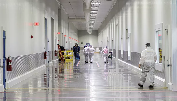
Every plant, regardless of its age, can maintain clean air, and it starts with simple practices. “Many food processing plants employ stringent uniform and locker room standards [such as plant-issued footwear and sanitary over-garments] to minimize [the amount of] airborne contaminants entering the buildings,” says Stellar’s Facemyer.
“Airflow systems are often complicated and not intuitive,” says Mangin, “but training employees can help a system to do its job and not overtax it with contaminants it was not designed to handle.” Vestibules and automatic doors are probably the most common methods to address issues caused by employees leaving doors open. However, a good control system that compensates automatically for temperature, humidity, filtration and pressure changes under different operating conditions can go a long way in solving these problems. The system also should include sensors and alarms to alert employees when doors are open for longer than expected periods.
Processors also can limit access to specific work areas through the use of doors that require card readers to open them. They can use automation to a greater extent to move products and ingredients from zone to zone. And, they can take a stronger stance on rework coming out of critical zones. According to Hixson’s Follmer, rather than expecting humans or building automation systems to fix all their airflow issues, processors can take a number of approaches that can have a positive impact on airflow.
References:
“Pressurization of Critical Process Areas,” Bruce A. Paulson, EVAPCO, Inc.
“Handle air with care,” Food Engineering, May 2012, www.foodengineeringmag.com/articles/89344-handle-air-with-care.
For more information:
Mike Follmer, Hixson Architecture & Engineering, 513-241-1230, mfollmer@hixson-inc.com, www.hixson-inc.com
Mark A. Hoffman, SSOE Group, 651-726-7660, mark.hoffman@ssoe.com, www.ssoe.com
Donna Lorenzen, The Austin Company, 949-451-9000, donna.lorenzen@theaustin.com, www.theaustin.com
Joe Sunnarborg, EVAPCO, 507-446-8005, joes@evapcomn.com, www.evapco.com
Frank Mangin, Haskell, 904-791-4500, frank.mangin@haskell.com, www.haskell.com
Mark Davidson, Camfil USA, 888-599-6620, mark.davidson@camfil.com, www.camfil.com
Luke Facemyer, Stellar, 904-260-2900, lfacemyer@stellar.net, www.stellar.net
Looking for a reprint of this article?
From high-res PDFs to custom plaques, order your copy today!